
Propeller swept area: disc formula and the area actually swept
The swept area of a propeller is the area of the disc the blades describe as they rotate: S = π × R², where R is the blade tip radius. Because the blade root sits at some distance from the shaft, the area actually swept is a little smaller: S = π × (R² − r²), where r is the blade root radius. It is the reference quantity of a propeller or a turbine, because it sets how much fluid the rotor passes.
In this page:
- Propeller swept area formula
- The area actually swept
- Area covered by the blades
- Covered area ratio and optimum rotation speed
- Why the swept area sets the power
1: Propeller swept area formula
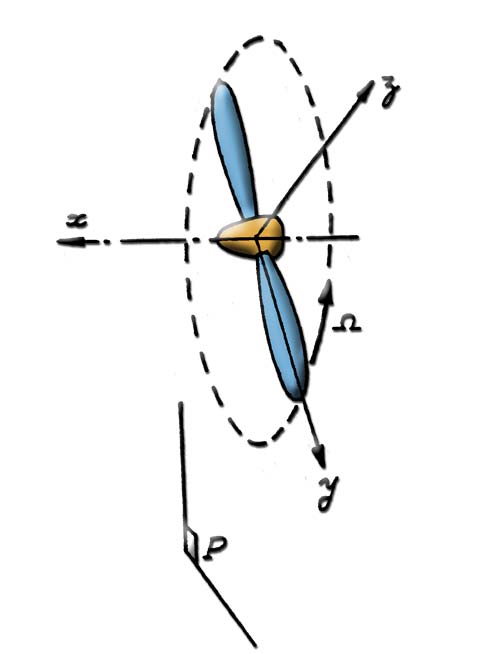
The plane of rotation P of the propeller: the disc swept by the blades lies in it.
P represents the plane of rotation of the propeller. The disc swept by the blades lies in this plane, and the swept area, or swept disc, is:
- swept area = π × (blade tip radius)², with π ≈ 3.14.
The radius is in metres, the area in square metres. For a propeller 2 m in diameter, for example, the radius is 1 m and the disc is 3.14 m².
2: The area actually swept
The area actually swept by the propeller is in fact smaller, because the blade root is usually placed at some distance from the centre of the propeller: at the centre, the hub takes the space.
- real swept area = π × (blade tip radius)² − π × (blade root radius)².
With the same example (blade tip radius 1 m) and a blade root radius of 0.1 m, the real swept area is π × (1² − 0.1²), that is 3.11 m². The difference is small for a small hub, but it grows quickly with the blade root radius, since it varies with its square.

The Heliciel panel under the chord graph: blades surface (0.9 m² here), swept area (2.5 m², 2.47 m² in the tooltip) and their ratio (0.35).
3: Area covered by the blades
The developed area of a blade is the sum of the average areas of the elements of the blade. Each average area is calculated from the average chord of the element:
- average chord of the element = (chord of the base profile of the element + chord of the tip profile of the element) / 2;
- distance between elements = (blade tip radius − blade root radius) / number of elements;
- average area of the element = (average chord of the element) × (distance between elements).
The area covered by the propeller is the sum of the areas of the blades:
- area covered by the propeller = sum of the average areas of the elements × number of blades.
Each element behaves here like a small trapezoid, as wide as the average chord and as tall as the distance between two profiles. Heliciel adds these trapezoids over the whole blade, then multiplies by the number of blades.
4: Covered area ratio and optimum rotation speed
The covered area ratio compares the area covered by the blades with the swept area: a propeller with narrow blades covers little, a propeller with wide and numerous blades covers a lot. This ratio places a decisive constraint on the optimum rotation speed. One of the key factors that limit the rotation speed is indeed the interaction between the blades: a blade works in the wake of the previous one. Optimizing the rotation speed of the propeller therefore involves finding the optimum number of blades.

The fluid passes between the blades: depending on the rotation speed, the apparent wind is too fast, appropriate, or zero for the profile.
5: Why the swept area sets the power
For a wind turbine or a tidal turbine, the power of the fluid passing through the disc is P = ½ × ρ × S × V³, where ρ is the fluid density (kg/m³), S the swept area (m²) and V the fluid speed (m/s). The rotor captures only part of this power: at best 16/27, about 59%, according to the Betz limit. Doubling the swept area therefore doubles the available power, and doubling the diameter multiplies it by four.
For a propulsive propeller, disc theory gives the opposite relation. For a given thrust T, the minimum power to give to the fluid is T × √(T / (2 × ρ × S)), a formula of actuator disc theory (ideal propeller, no losses). The larger the swept area, the less power is needed for the same thrust: this is why a large slow rotor beats a small fast rotor at the same thrust.
To go further, we can see how Heliciel splits the blade into elements in the page on propeller geometry, or set the number of blades and the rotation speed with the page on optimizing rotation speed and number of blades.
 Global site map
 Mecaflux
 Tutorials Mecaflux Pro3D
 Tutorials Heliciel
 Tutorials Heliciel PRO CFD
 Mecaflux Store
 Compare software functions
 Quotes, Orders, Payment Methods
 project technical studies